Thứ Năm, 15 tháng 10, 2020

MÁY KIỂM TRA ĐỘ BỀN VẬT LIỆU

MÁY KIỂM TRA ĐỘ BỀN VẬT LIỆU 


* Phạm vi ứng dụng: Tất cả các loại vật liệu công nghiệp kim loại, plastic, màng , bao bì , composite , dây đai...

* Phạm vi kiểm tra :  độ bền kéo, nén , uốn ..

* Phạm vi tác dụng lực : 1kN - 300kN , mở rộng theo tùy chon khách hàng

  Thiết bị thiết kế đơn giản, dễ sử dụng cho độ chính xác và khả năng phân tích cao bằng đồ thị. 

  Bộ điều khiển có chức năng di chuyển con trượt di chuyển lên xuống để thay đổi lực theo yêu cầu kiểm tra của từng loại vật liệu.

Bảng thông số kĩ thuật cho từng loại model tùy thuộc vào qui mô từ phòng LAB đến sản xuất công nghiệp.


Video mô phỏng  thí nghiệm với máy 5ST

https://www.youtube.com/watch?v=mjJn5BF6784


Mọi chi tiết thắc mắc xin vui lòng liên hệ về

Mr Ankiez Lieu

Hotline : 0943039340

Email: wetest1809@gmail.com

Một số hình ảnh về thiết bị 


Share:

Flow marks, troubleshooting


                  Flow marks, troubleshooting

A flow mark or halo, is a surface defect in which circular ripples or wavelets appear near the gate.

Ripples, a similar defect, appear as small fingerprint-like waves near the edge or at the end of the flow.


Causes

  • Material freezing near the gate. Low melt or mold temperature, and low ram speed can result in cold material entering the cavity. This can cause the partly solidified material to take on the form of the flow pattern.


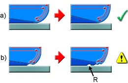
    Ripples caused by low temperature

    .

    a normal fountain flow with no ripples, b flow causing ripples (R).

  • Insufficient material compensation. Early gate freeze-off or low packing pressure may not pack the cavity properly. The material near the gate then freezes while maintaining the form of the flow pattern.

Remedies

  • Optimize the cold well. Design the cold well in the runner system to trap the cold material during the filling phase. The proper length of the cold well is usually equal to that of the runner diameter.

  • Optimize the runner system design. A restrictive runner system design can result in premature gate freeze-off. It can however, increase shear heating for better melt flow.

  • Increase the mold and melt temperature.

  • Optimize packing pressure.

Solving one problem can often introduce other problems to the injection molding process. Each option hence requires consideration of all relevant aspects of the mold design specification.


Share:

Unbalanced flow, troubleshooting


Unbalanced flow, troubleshooting

Unbalanced flow is plastic completely filling some flow paths in the mold before other flow paths have filled.

Unbalanced flow can be the cause of many molding problems such as flashing, short shots, high cycle time, density differences throughout the part, warpage, air traps and extra weld lines.

Flow is balanced when all the extremities of the mold fill at the same time.

To recognize unbalanced flow, you need to recognize the different flow paths in the mold. These are the different routes that the plastic takes throughout the cavity.

The following part contains three fundamental flow paths (shown as red arrows).
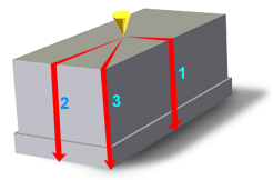


Each flow path is of a different length. Therefore, if the part has uniform thickness, flow path 1 will fill first, followed by flow path 2, followed by flow path 3.

To identify unbalanced flow, use either the fill preview or the fill time result.

What to do

By altering the thickness of regions within the part, flow can be hastened or delayed in certain directions to help balance flows. In the above diagram, varying the part thickness and creating flow leaders and deflectors, thinning flow path 1 and thickening flow path 3, is the answer. These variations in thickness are known as Flow Leaders or Flow Deflectors.

In other examples it is often necessary to consider the position of the polymer injection location, or the number of polymer injection locations.

For example, if you choose a single injection location that defines some flow paths to be three or four times the length of others, then it is almost impossible to balance flows. Try moving the polymer injection location to a position that will define similar length flow paths. Alternatively, visualize the cavity in smaller, more manageable sections. Then use multiple injection locations, one per sub-section.

For a multi-cavity part, balance flows in each cavity first, then proceed to alter runner dimensions to ensure that:

  • All cavities fill at approximately the same time, with the same pressure.

  • The temperature at the end of fill shows uniform distribution in each cavity, predicting uniform shrinkage, and acceptable weld line quality.

  • The shear stress in each cavity (ignore runners) is less than the recommended limit for the material chosen.


Share:

Troubleshooting flow problems


Troubleshooting Melt flow problems


Flow problems manifest themselves in a variety of ways, including overpacking, insufficient packing, and visual defects.

Share:

THUẬT NGỮ CHUYÊN NGÀNH NHỰA - PLASTIC

       THUẬT NGỮ CHUYÊN NGÀNH NHỰA - PLASTIC

Tiếng Việt

Anh

Phụ gia Additive
Chất chống oxy hóa Antioxidant
Tác nhân chống tĩnh điện Antistatic agent
Nòng xy-lanh Barrel
Thổi khuôn Blow molding
Thổi màng Blown Film
Cán láng (xuất tấm) Calandering
Chất xúc tác Catalyst
Đùn kết hợp Co-extrusion
Dây chuyền đùn kết hợp Co-extrusion Line
Chất tạo màu Colourant
Vật liệu composite Composite Material
Hợp chất Compound
Polymer đồng trùng hợp Copolymer
Xử lý bề mặt theo công nghệ Corona (điện hóa) Corona Treatment
Tính chất phân hủy Degradable
Khuôn tạo hình Die
Thiết bị Equipment (Machine)
Polystyrene trương nở được Expandable Polystyrene (EPS)
Đùn Extrusion
Sợi Fibre
Chất hãm cháy Flame Retardent
Polymer nền fluorocarbon Fluoropolymers
Bọt xốp Foam
Chất dẻo gia cường bằng sợi thủy tinh (FRP) Glass Fibre Reinforced Plastics
Phễu Hopper
Rãnh dẫn nhựa nóng Hot runner
Độ bền va đập Impact Strengths
Chất ức chế Inhibitor
Ép phun – thổi Injection Blow Moulding
Ép phun – đúc ép Injection Compression Moulding
Ép phun Injection Moulding
Máy ép phun Injection Moulding Machine
Cán mỏng Laminate
Chất bôi trơn Lubricant
Hạt màu masterbatch Masterbatch
Chỉ số chảy Melt Flow Index
Khuôn Mould
Tác nhân chống dính khuôn Mould Release Agent
Tạo hạt Pellet
Hạt màu Pigment
Chất hóa dẻo Plasticizer
Chất dẻo Plastics
Polyacetal (POM) Polyacetal (POM)
Polyamide (PA) Polyamide (PA)
Polyamide Imide (PAI) Polyamideimide (PAI)
Poly Butylene Terephthalate (PBT) Polybutylene Terephthalate (PBT)
Polycarbonate (PC) Polycarbonate (PC)
Poly Ester Polyester
Polyether Etherketone (PEEK) Polyether Etherketone (PEEK)
Poly Ête Imide Polyether Imide
Polyetherssulphone (PES, PESU) Polyetherssulphone (PES, PESU)
Polyethylene (PE) Polyethylene (PE)
Polyethylene Terephthalate (PET) Polyethylene Terephthalate (PET)
Polymethylmethacrylate (PMMA) Polymethylmethacrylate (PMMA)
Polyphenylene ether (PPE) Polyphenylene ether (PPE)
Polypropylene (PP) Polypropylene (PP)
Polystyrene (PS) Polystyrene (PS)
Polytetrafluoro Ethylene (PTFE Polytetrafluoro Ethylene (PTFE)
Polyurethane (PU) Polyurethane (PU)
Polyvinyl Chloride (PVC) Polyvinyl Chloride (PVC)
Công nghệ Pultrusion Pultrusion
Nguyên liệu Raw Material
Tái sinh Recycle
Chất dẻo được gia cường Reinforced Plastics
Nhựa Resin
Cứng, không linh động Rigid
Đúc khuôn quay Rotational Moulding
Tấm Sheeting, Sheet
Co rút Shrinkage
Dung môi Solvent
Chất ổn định Stabaliser
Lỗ xốp cấu trúc Structural Foam
Tạo hình nhiệt Thermoforming
Nhiệt rắn Thermoset
Máy đùn 2 trục vít Twin Screw Extruder
Tạo hình chân không Vacuum Forming
Độ nhớt Viscosity
HànWelding
Share:

Độ cứng Rockwell

Tổng số lượt xem trang